
By John J. Dougherty, DFP Foundation Products, LLC
 The
advantages of a tapered shape for a pile have been known for many
years.
Some soil conditions that would otherwise not carry much load using a
straight-sided
pile will carry a substantially higher load when the pile is
tapered.
The combination of bearing and frictional resistance produced by the
wedge
shape of the taper is greater than the side friction and end bearing of
a cylindrical pile.
The
advantages of a tapered shape for a pile have been known for many
years.
Some soil conditions that would otherwise not carry much load using a
straight-sided
pile will carry a substantially higher load when the pile is
tapered.
The combination of bearing and frictional resistance produced by the
wedge
shape of the taper is greater than the side friction and end bearing of
a cylindrical pile.
Timber piles were the first tapered piles. Perhaps the designer of the tree engineered the shape of the trunk with piles in mind. Using the trunk as a pile must have come easily to ancient pile drivers; placing the small end down was obviously a better way to drive a tree trunk into the ground.
There have been other tapered piles to come to the market. The Raymond Standard Taper pile that was a true tapered pile along with the Step-Taper pile have both disappeared from the scene. The Union Metal Monotube is still available although the product is now owned by another entity since the demise of the Union Metal Manufacturing Co. All of the tapered products produced as tubular steel piles, that are filled with concrete after installation, can be manufactured in sheet metal gage thickness only. The one exception to that is the patented TAPERTUBE® PILE.
 Engineers
today are striving to increase pile capacities in order to reduce
costs.
Increased pile loads reduce the number of piles required.
Reducing
the number of piles usually results in an added cost benefit by
reducing
pile cap sizes. Increased pile capacities require piles to be
driven
harder with more efficient equipment. This has created a need for
a stronger and stiffer, more reliable pile that is less likely to be
damaged
during driving.
Engineers
today are striving to increase pile capacities in order to reduce
costs.
Increased pile loads reduce the number of piles required.
Reducing
the number of piles usually results in an added cost benefit by
reducing
pile cap sizes. Increased pile capacities require piles to be
driven
harder with more efficient equipment. This has created a need for
a stronger and stiffer, more reliable pile that is less likely to be
damaged
during driving.
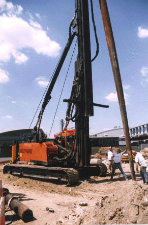
An improved tapered steel pile had been the subject of discussion between Stanley Merjan of Underpinning & Foundation Constructors, Inc. (UFC) and myself for a number of years. The opportunity to develop and test such a pile came with the advent of the work to build the Light Rail System at John F. Kennedy International Airport in Queens, New York. The job would require more than 6,000-150 ton capacity piles to be driven through upper layers of fill and peat, and into a sand stratum (typical “N” values from 10 to 30) that extends to depths of more than 100 ft. Slattery-Skanska, the General Contractor for the Light Rail system, decided to implement an extensive pile testing program to determine the most suitable pile to be used for the job. UFC, the pile contractor selected for this work, offered to test the TAPERTUBE ™ pile in addition to cylindrical pipe piles and tapered fluted piles as originally planned. The test program included driving and load testing piles at three sites along the route of the LRS within the airport. All of the piles were driven with a Junttan HHK-7 hydraulic hammer delivering more than 45,000 ft-lbs of energy.
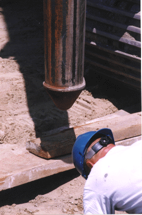
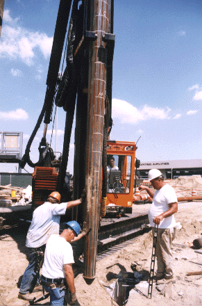
The TAPERTUBE piles tested at the airport were configured with a 25’ long tapered section having a bottom diameter of 8”, top diameter of 18”, fabricated with 0.312”, 50 ksi steel as a 12-sided polygon. A cast steel point was welded to the bottom of the taper, and the polygonal shape was mechanically circularized at the top of the taper. The extension, 18” dia. X 0.375” steel pipe, was butt welded to the top of the tapered section. After driving, the piles were filled with 5,000 p.s.i. concrete. (This is the same pile design used on all JFK Projects with loads from 150 tons to 210 tons.)
 The
results of the testing (see attached tables) conclusively showed the
superiority
of the tapered piles over the cylindrical piles. Both of the
tapered
pile types produced excellent test results. However, the
TAPERTUBE
piles demonstrated some significant advantages as compared to the
fluted
piles. Some of these included lower driving stresses with no
deformation
of the butt during driving and a butt welded splice joining the tapered
section to the pipe that developed the full strength of the pile.
The heavier wall thickness of the TAPERTUBE pile required a smaller
reinforcing
steel cage in the top of the pile (for lateral capacity) and eliminated
the need for corrosion protection. The fluted piles having a
thickness
of 0.239” (3 gauge) yielded driving stresses that were close to the
yield
strength of the steel and required welded plate reinforcement to
prevent
buckling of the butt during driving. The fluted cylindrical
extension
telescoped into the tapered section and was joined by a lap weld that
did
not develop the full strength of the section, a heavy cage was required
in the top of the pile, and a 16 mil thick coal tar epoxy coating for
the
top 35 feet of the pile to prevent corrosion. Furthermore, all of
the TAPERTUBE piles remained dry after driving; several fluted piles
leaked
water, apparently the result of split seams.
The
results of the testing (see attached tables) conclusively showed the
superiority
of the tapered piles over the cylindrical piles. Both of the
tapered
pile types produced excellent test results. However, the
TAPERTUBE
piles demonstrated some significant advantages as compared to the
fluted
piles. Some of these included lower driving stresses with no
deformation
of the butt during driving and a butt welded splice joining the tapered
section to the pipe that developed the full strength of the pile.
The heavier wall thickness of the TAPERTUBE pile required a smaller
reinforcing
steel cage in the top of the pile (for lateral capacity) and eliminated
the need for corrosion protection. The fluted piles having a
thickness
of 0.239” (3 gauge) yielded driving stresses that were close to the
yield
strength of the steel and required welded plate reinforcement to
prevent
buckling of the butt during driving. The fluted cylindrical
extension
telescoped into the tapered section and was joined by a lap weld that
did
not develop the full strength of the section, a heavy cage was required
in the top of the pile, and a 16 mil thick coal tar epoxy coating for
the
top 35 feet of the pile to prevent corrosion. Furthermore, all of
the TAPERTUBE piles remained dry after driving; several fluted piles
leaked
water, apparently the result of split seams.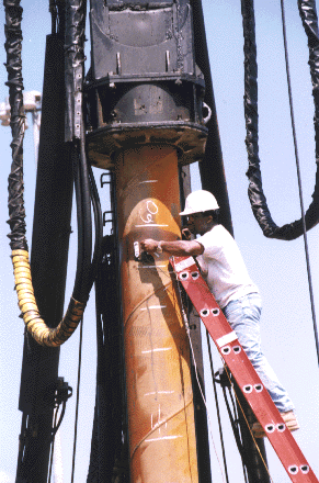 Evaluation
of the tests for the newly developed TAPERTUBE piles was not completed
by the time it was necessary to start production pile driving for the
LRS.
The fluted piles, in common use at JFK for many years, were chosen for
the section of the work within the airport. Within several months
the contract for 1,300 piles at the British Airways Terminal at JFK was
bid, and a UFC proposal to substitute 150 ton capacity TAPERTUBE piles
for 150 ton capacity fluted piles (which were already tested for this
job)
was accepted on the basis of the results of the LRS test program.
Evaluation
of the tests for the newly developed TAPERTUBE piles was not completed
by the time it was necessary to start production pile driving for the
LRS.
The fluted piles, in common use at JFK for many years, were chosen for
the section of the work within the airport. Within several months
the contract for 1,300 piles at the British Airways Terminal at JFK was
bid, and a UFC proposal to substitute 150 ton capacity TAPERTUBE piles
for 150 ton capacity fluted piles (which were already tested for this
job)
was accepted on the basis of the results of the LRS test program.
Soon after the start of the British Airways work UFC was called in to complete the first phase of the piling for the International Arrivals Building (IAB) at JFK where 1,500-180 ton capacity fluted piles were being driven. UFC successfully completed this stage of the work with the fluted piles. However, it was evident that the maximum 3 gauge steel thickness of these piles was inadequate to accommodate the driving stresses generated by the 180 ton capacity requirement. A number of piles collapsed and many leaked due to the hard driving. To, avoid these problems UFC proposed the substitution of TAPERTUBE piles for the next phase which required 1,000 piles, and the proposal was accepted.
The testing and subsequent installation of production piles for both British Airways and the IAB went very well. Pile installation rates averaged 12 or more per 8 hour shift (compared to less than 6 per shift for the prior work at the IAB), no piles were damaged, and none leaked.
These successful installations demonstrated the benefits of the TAPERTUBE piles, and resulted in the review of the use of TAPERTUBE piles for the remaining 1,700 piles for the Light Rail System. This work extended beyond the airport limits along the median of the Van Wyck Expressway to the terminus at Jamaica Station. The TAPERTUBE tests performed by UFC indicated that higher capacities would be viable for this extension. 200 ton capacity piles were proposed and successfully tested. The increased capacity reduced the number of piles required by 25%, resulting in significant savings of money, but more important, shortened by two months the time required to construct the work along an exceptionally busy stretch of roadway.
Other jobs that are currently under way with TAPERTUBE piles include the roadway structures for American Airlines at JFK (650-180 ton piles) and the new terminal for the Light Rail System at Jamaica Station (300-210 ton capacity piles). The requisite driving resistance that is required with the HHK-7 hammer range from about 17 blows per foot for 150 ton capacity to about 30 blows per foot for 210 ton capacity. Lateral capacities of 20 tons and uplift capacities of 50 tons have been established for these piles.
A Summary
of
some of the early testing is shown below.
COMPRESSION TESTS
|
|
|
|
|
(TONS) |
CAP (TONS) |
|
|
|
|
|
|
|
|
|
|
|
|
|
|
|
|
|
|
|
|
|
|
|
|
|
|
|
|
|
|
|
|
|
|
|
|
|
|
|
|
|
|
|
|
|
|
|
|
|
|
|
|
|
|
|
|
|
LATERAL TESTS
|
|
|
|
|
|
|
|
|
|
|
|
|
|
|
|
|
|
|
|
|
|
|
|
|
|
|
|
UPLIFT TESTS
|
|
|
|
|
|
|
|
|
|
|
|
|
|
|
|
|
|
|
|
|
|
|
|
|
|
|
|
|
|
|
|
|
|
|
|
|
|
|
|
|
|
TAPERTUBE piles can be made in various shapes and sizes to accommodate soil and capacity considerations. The polygonal tapered lower section usually has 12 sides, with bottom and top diameters that may vary from 8 inches to 24 inches over a length of 10 to 35 feet. Grade 50 steel is used for this section with a thickness that can range from 3/16” to 5/8”. Circularization of the top of the polygon conforms to the diameter of the steel pipe extension, and a butt weld assures development of the full strength of the piling elements. These piles have demonstrated their effectiveness in granular soils. Past use of tapered piles in cohesive soils indicate the probable success of TAPERTUBE piles for these conditions, but no tests have been done to date.
In the early months of the year (2001) I was contacted by a large and well respected engineering firm based in Boston, MA. They had seen information on our web-site (www.pilelineonline.com) about TAPERTUBE PILES.
There was a marine project that they were involved with where 12 ¾” diameter pipe piles were driven to anticipated tip elevations and resistance with a diesel hammer. While warming up the hammer on a previously accepted pile this pile was observed to have lost some of its initial resistance, thus losing some of its capacity. Other piles were then retapped with similar results.
We were provided with a copy of the soil borings in order to evaluate the viability of the TAPERTUBE pile to carry the required load without capacity loss. The borings showed silty sands (SM) at a depth of –30’ having “N” values of 100 to 175 blows, or sufficiently dense to yield a safe 80 ton capacity for the 12 ¾” piles. Evidently this was not the case so it became necessary to find a suitable alternative.
We suggested the use of TAPERTUBE piles instead of the pipe piles. A total of 12 piles were furnished and test-driven with PDA measurements made to evaluate pile capacity. Six of the piles had 8”x 14” x 15’ tapered bottoms attached to 14” pipe extensions and six piles had 8” x 12 ¾” x 13’ tapered bottoms attached to 12 ¾” pipe extensions. These piles were retapped without any loss in capacity. As a result of this testing two hundred Tapertube piles have been ordered for the job. The work is now being done and the contractor has told us that the installation is proceeding smoothly without any problems.
We have great expectations for this product. It has proven to be tough, trouble free, and easy to use.
More information about TAPERTUBE is available by calling John Dougherty at 201-337-5748. The email address is John@tapertube.com.
© Copyright 2001-2023
Pileline Publishing
![]()
![]()